
Air choke LD 200
Air reactor with copper/disc winding Description Air reactors are used when a particularly high linearity is required. By its relatively simple structure, they are not only compact, but also very stable. With our expertise, REO air chokes maintain their full functionality even under extreme conditions. With our expertise, the REO air reactors perform to the required standard, even in the most arduous conditions. REO Mix & Match principle With REO Mix & Match you can choose from a wide range of of options – combine the various options in order to always get the best product for your application. REO is able to offer different designs and winding techniques, a variety of conductor materials and structures. Depending on the specific requirements, we are able to produce an optimal solution by combining these parameters to provide the perfect solution. Optional Layer winding/Disc winding Aluminium, Copper or aluminium + copper Protections: Paint coating, protective coating, housing or REO Xtreme Cooling fan/unit Sensors: Switch NO / NC, PT100, NTC, PTC Advantages No saturation Wide range of material selection Special protective coating High linearity L (i) Very good mechanical strength No hysteresis Optimal weight by forced air cooling Directional air flow through GRP conduits Very efficient liquid cooling option (waveguide) Able to be universally applied. Technical specification Frequency of the current: DC and AC Tolerances: + 10 / – 10 %, + 5 / – 5 % Taps: By default, no taps (available on request) Insulation: F or H Cooling method and cooling liquid according to IEC 60310: AN, AF or WF Test voltage: up to 12kV 60s 50Hz, up to 25kV 1,2/50µs Mounting: Suspended, vertical or horizontal Mechanical strength, mechanical simulation (FEM): EN 12663 Shock – and vibration stress: IEC 61373 Kat. 1 Kl. B Rated current: 100 – 700 A Type Inductance (mH) Cooling 3 m/s Cooling 5 m/s Cooling 8 m/s I [A] magn. Energy [J] P [kVA] at 20°C I [A] magn. Energy [J] P [kVA] at 20°C I [A] magn. Energy [J] P [kVA] at 20°C LD 200/100/1 1 100 5 0,4 140 9,8 0,7 180 16,2 1,2 LD 200/200/1 1 200 20 0,9 270 36,5 1,6 33o 54,5 2,4 LD 200/400/1 1 400 80 2,1 530 140,5 3,6 660 217,8 5,6 LD 200/700/1 1 700 245 3,4 850 361,3 5,6 1000 500 13,2 LD 200/100/2 2 100 10 0,7 130 16,9 1,6 150 22,5 1,4 LD 200/200/2 2 200 40 1,4 250 62,5 2,1 320 102,4 3,5 LD 200/400/2 2 400 160 3,3 500 250 5,1 600 360 7,3 LD 200/700/2 2 700 490 5,4 950 902,5 9,9 1100 1210 13,2 LD 200/100/4 4 100 20 1,1 120 28,8 1,6 140 39,2 2,2 LD 200/200/4 4 200 80 2,1 250 125 3,3 300 180 4,7 LD 200/400/4 4 400 320 5,1 500 500 7,9 600 720 11,4 LD 200/700/4 4 700 980 8,2 950 1805 15,1 1150 2645 22,1 LD 200/100/8 8 100 40 1,8 120 57,6 2,5 140 78,4 3,4 LD 200/200/8 8 200 160 3,3 250 250 5,2 300 360 7,5 LD 200/400/8 8 400 640 7,7 500 1000 12,1 600 1440 17,4 DIMENSIONS IN MM Type B (mm) H (mm) T (mm) Copper (kg) Weight (g) LD 200/100/1 300 300 110 11,1 15 LD 200/200/1 350 350 130 24,3 32 LD 200/400/1 420 420 185 57,2 68 LD 200/700/1 450 450 325 158,4 173 LD 200/100/2 300 300 120 12,5 17 LD 200/200/2 350 350 180 37,6 46 LD 200/400/2 400 400 270 90 103 LD 200/700/2 500 500 475 250,8 286 LD 200/100/4 300 300 170 19,7 26 LD 200/200/4 350 350 240 58,1 71 LD 200/400/4 420 420 360 140,6 157 LD 200/700/4 550 550 550 381,8 415 LD 200/100/8 300 300 200 31 40 LD 200/200/8 400 400 320 92,3 107 LD 200/400/8 500 500 365 214,5 235
Air chokes LD 120

Air reactor with copper/disc winding Description Air reactors are used when a particularly high linearity is required. By its relatively simple structure, they are not only compact, but also very stable. With our expertise, REO air chokes maintain their full functionality even under extreme conditions. With our expertise, the REO air reactors perform to the required standard, even in the most arduous conditions. REO Mix & Match principle With REO Mix & Match you can choose from a wide range of of options – combine the various options in order to always get the best product for your application. REO is able to offer different designs and winding techniques, a variety of conductor materials and structures. Depending on the specific requirements, we are able to produce an optimal solution by combining these parameters to provide the perfect solution. Optional Layer winding/Disc winding Aluminium, Copper or aluminium + copper Protections: Paint coating, protective coating, housing or REO Xtreme Cooling fan/unit Sensors: Switch NO / NC, PT100, NTC, PTC Advantages No saturation Wide range of material selection Special protective coating High linearity L (i) Very good mechanical strength No hysteresis Optimal weight by forced air cooling Directional air flow through GRP conduits Very efficient liquid cooling option (waveguide) Able to be universally applied. Technical specification Frequency of the current: DC and AC Tolerances: + 10 / – 10 %, + 5 / – 5 % Taps: By default, no taps (available on request) Insulation: F or H Cooling method and cooling liquid according to IEC 60310: AN, AF or WF Test voltage: up to 12kV 60s 50Hz, up to 25kV 1,2/50µs Mounting: Suspended, vertical or horizontal Mechanical strength, mechanical simulation (FEM): EN 12663 Shock – and vibration stress: IEC 61373 Kat. 1 Kl. B Rated Current: 200 – 1000A Type Inductance (mH) Cooling 3 m/s Cooling 5 m/s Cooling 8 m/s I [A] magn. Energy [J] P [kVA] at 20°C I [A] magn. Energy [J] P [kVA] at 20°C I [A] magn. Energy [J] P [kVA] at 20°C LD 120/200/0,2 0,2 200 4 0,4 240 5,8 0,6 285 8,1 0,8 LD 120/400/0,2 0,2 400 16 0,9 510 26 1,5 610 37,2 2,1 LD 120/700/0,2 0,2 700 49 1,3 860 74 2 1030 106,1 2,9 LD 120/1000/0,2 0,2 1000 100 2,2 1170 136,9 3 1400 196 4,2 LD 120/200/0,5 0,5 200 10 0,7 245 15 1 295 21,8 1,5 LD 120/400/0,5 0,5 400 40 1,6 510 65 2,5 600 90 3,5 LD 120/700/0,5 0,5 700 122,5 2,4 870 189,2 3,7 1030 265,2 5,2 LD 120/1000/0,5 0,5 1000 250 3,6 1200 360 5,1 1440 518,4 7,4 LD 120/200/1 1 200 20 1 255 32,5 1,6 300 45 2,2 LD 120/400/1 1 400 80 2,4 500 125 3,7 600 180 5,4 LD 120/700/1 1 700 245 3,7 870 378,5 5,8 1030 530,5 8,1 LD 120/1000/1 1 1000 500 5,5 1200 720 7,9 1420 1008,2 11,1 LD 120/200/2 2 200 40 1,6 250 62,5 2,4 300 90 3,5 LD 120/400/2 2 400 160 3,8 500 250 5,9 600 360 8,5 LD 120/700/2 2 700 490 5,8 870 756,9 8,9 1040 1081,6 12,7 LD 120/1000/2 2 1000 1000 8,5 1190 1416,1 12,1 1410 1988,1 17 LD 120/200/4 4 200 80 2,3 255 130,1 3,8 300 180 5,3 LD 120/400/4 4 400 320 6,3 500 500 9,8 600 720 14,1 LD 120/700/4 4 700 980 8,6 810 1312,2 13,4 1040 2163,2 19,1 LD 120/1000/4 4 1000 2000 12,7 1250 3125 19,9 1500 4500 28,7 LD 120/200/8 8 200 160 3,6 250 250 5,6 300 360 8,1 LD 120/400/8 8 400 640 9,3 500 1000 14,5 600 1440 20,8 LD 120/700/8 8 700 1960 13,5 870 3027,6 20,9 1050 4410 30,4 Dimensions in mm Type B [mm] H [mm] T [mm] Cooper [kg] Weight [g] LD 120/200/0,2 250 250 150 6,6 11 LD 120/400/0,2 350 350 180 16 25 LD 120/700/0,2 350 350 280 44,6 54 LD 120/1000/0,2 400 400 420 77,2 92 LD 120/200/0,5 300 300 180 11,9 18 LD 120/400/0,5 400 400 210 27,8 38 LD 120/700/0,5 400 400 350 80 93 LD 120/1000/0,5 500 500 360 127 147 LD 120/200/1 350 350 170 17,8 26 LD 120/400/1 450 450 240 39,1 57 LD 120/700/1 450 450 460 125 139 LD 120/1000/1 550 550 490 197 222 LD 120/200/2 400 400 190 26,9 37 LD 120/400/2 450 450 360 67,5 83 LD 120/700/2 450 450 580 192 217 LD 120/1000/2 550 550 640 305 341 LD 120/200/4 400 400 230 40,6 55 LD 120/400/4 450 450 530 109 129 LD 120/700/4 550 550 620 289 326 LD 120/1000/4 600 600 820 503 555 LD 120/200/8 450 450 320 64,1 81 LD 120/400/8 500 500 600 169 192 LD 120/700/8 550 550 830 453 506
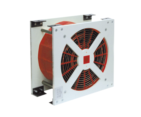
Air choke LD 110

Air choke with aluminium/layer winding Description Air reactors are used when a particularly high linearity is required. By its relatively simple structure, they are not only compact, but also very stable. With our expertise, REO air chokes maintain their full functionality even under extreme conditions. With our expertise, the REO air reactors perform to the required standard, even in the most arduous conditions. REO Mix & Match principle With REO Mix & Match you can choose from a wide range of of options – combine the various options in order to always get the best product for your application. REO is able to offer different designs and winding techniques, a variety of conductor materials and structures. Depending on the specific requirements, we are able to produce an optimal solution by combining these parameters to provide the perfect solution. Optional Layer winding/Disc winding Aluminium, Copper or aluminium + copper Protections: Paint coating, protective coating, housing or REO Xtreme Cooling fan/unit Sensors: Switch NO / NC, PT100, NTC, PTC Advantages No saturation Wide range of material selection Special protective coating High linearity L (i) Very good mechanical strength No hysteresis Optimal weight by forced air cooling Directional air flow through GRP conduits Very efficient liquid cooling option (waveguide) Able to be universally applied. Technical Data Frequency of the current: DC and AC Tolerances: + 10 / – 10 %, + 5 / – 5 % Taps: By default, no taps (available on request) Insulation: F or H Cooling method and cooling liquid according to IEC 60310: AN, AF or WF Test voltage: up to 12kV 60s 50Hz, up to 25kV 1,2/50µs Mounting: Suspended, vertical or horizontal Mechanical strength, mechanical simulation (FEM): EN 12663 Shock – and vibration stress: IEC 61373 Kat. 1 Kl. B Rated current: 50 – 1000 A Inductance: 0,2 – 8 mH Technical specification Type Inductance [mH] Cooling 3 m/s Cooling 5 m/s Cooling 8 m/s I [A] magn. Energy [J] P [kVA] at 20°C I [A] magn. Energy [J] P [kVA] at 20°C I [A] magn. Energy [J] P [kVA] at 20°C LD 110/70/0,2 0,2 70 0,49 0,2 87 0,8 0,3 105 1,1 0,4 LD 110/100/0,2 0,2 100 1 0,2 133 1,8 0,3 160 2,6 0,5 LD 110/200/0,2 0,2 200 4 0,4 240 5,8 0,6 290 8,4 0,8 LD 110/400/0,2 0,2 400 16 0,9 480 23 1,3 570 32,5 1,9 LD 110/700/0,2 0,2 700 49 1,5 820 67,2 2 980 96 2,9 LD 110/1000/0,2 0,2 1000 100 2,3 1210 146,4 3,4 1470 216,3 4,7 LD 110/50/0,5 0,5 50 0,625 0,2 60 0,9 0,3 70 1,3 0,4 LD 110/100/0,5 0,5 100 2,5 0,4 118 3,5 0,6 140 4,9 0,8 LD 110/200/0,5 0,5 200 10 0,7 235 13,8 1 280 19,6 1,4 LD 110/400/0,5 0,5 400 40 1,6 485 58,8 2,3 585 84,1 3,3 LD 110/700/0,5 0,5 700 122,5 2,5 820 168,1 3,6 970 235,2 5 LD 110/1000/0,5 0,5 1000 250 3,9 1230 378,2 5,9 1460 532,9 8,2 LD 110/50/1 1 50 1,25 0,3 60 1,8 0,5 72´3 2,7 0,7 LD 110/100/1 1 100 5 0,6 125 7,8 1 148 11 1,4 LD 110/200/1 1 200 20 1 240 28,8 1,5 290 42,1 2,2 LD 110/400/1 1 400 80 2,5 490 120,1 3,7 580 168,2 5,2 LD 110/700/1 1 700 245 3,8 830 344,5 5,3 980 480,2 7,4 LD 110/1000/1 1 1000 500 6 1240 768,8 9,3 1480 1095,2 13,2 LD 110/50/2 2 50 2,5 0,5 62 3,8 0,8 84 7,1 1,1 LD 110/100/2 2 100 10 1 122 14,9 1,5 145 21 2,1 LD 110/200/2 2 200 40 1,6 245 60 2,4 290 84,1 3,4 LD 110/400/2 2 400 160 3,9 485 235,2 5,7 575 330,6 8 LD 110/700/2 2 700 490 6 825 680,6 8,3 980 960,4 11,8 LD 110/1000/2 2 1000 1000 9,1 1230 1512,9 13,8 1450 2102,5 19,7 LD 110/50/4 4 50 5 0,8 62 7,7 1,2 73 10,7 1,6 LD 110/100/4 4 100 20 1,5 125 31,3 2,3 150 45 3,3 LD 110/200/4 4 200 80 2,4 245 120,1 3,6 290 168,2 5,1 LD 110/400/4 4 400 320 6,2 490 480,2 9,3 585 684,5 13,2 LD 110/700/4 4 700 980 9,2 830 1377,8 12,9 980 1920,8 18 LD 110/1000/4 4 1000 2000 13,8 1240 3075,2 21,2 1480 4380,8 30,2 LD 110/50/8 8 50 10 1,1 62 15,4 1,7 74 21,9 2,5 LD 110/100/8 8 100 40 2,2 130 67,6 3,7 155 96,1 5,2 LD 110/200/8 8 200 160 3,8 245 240,1 5,7 290 336,4 8 LD 110/400/8 8 400 640 9,4 490 960,4 14,1 580 1345,6 19,7 LD 110/700/8 8 700 1960 13,8 820 2689,6 19 980 3841,6 27,1 Dimensions in mm Type B [mm] H [mm] T [mm] Cooper [kg] Weight [g] LD 110/70/0,2 150 150 100 1 4 LD 110/100/0,2 200 200 120 2 5 LD 110/200/0,2 300 300 110 4,5 11 LD 110/400/0,2 350 350 190 10,9 21 LD 110/700/0,2 400 400 250 29 42 LD 110/1000/0,2 400 400 450 51,1 68 LD 110/50/0,5 200 200 80 1 4 LD 110/100/0,5 200 200 140 2,5 6 LD 110/200/0,5 300 300 200 8,3 15 LD 110/400/0,5 400 400 210 18,6 30 LD 110/700/0,5 400 400 380 52 69 LD 110/1000/0,5 500 500 420 84,7 106 LD 110/50/1 250 250 80 1,3 5 LD 110/100/1 250 250 130 3,7 8 LD 110/200/1 350 350 180 12,1 21 LD 110/400/1 450 450 250 29 43 LD 110/700/1 550 550 340 75,4 97 LD 110/1000/1 550 550 550 132 158 LD 110/50/2 250 250 100 2,1 6 LD 110/100/2 250 250 220 6 11 LD 110/200/2 400 400 230 18,8 29 LD 110/400/2 450 450 350 45,2 62 LD 110/700/2 500 500 500 119 142 LD 110/1000/2 550 550 660 200 232 LD 110/50/4 250 250 140 3,2 7 LD 110/100/4 300 300 200 9,8 15 LD 110/200/4 400 400 250 28,4 41 LD 110/400/4 450 450 520 72,3 95 LD 110/700/4 550 550 620 182 212 LD 110/1000/4 630 630 750 302 348 LD 110/50/8 250 250 160 4,7 10 LD 110/100/8 350 350
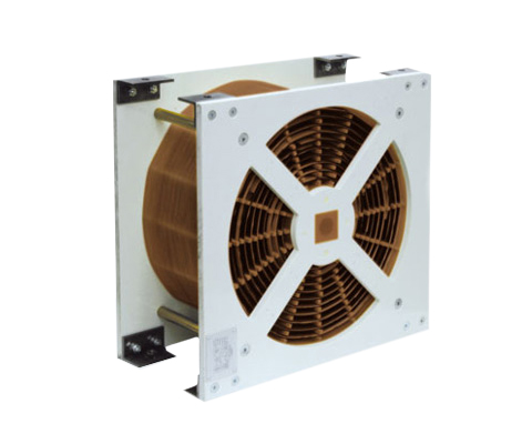
Air choke LD 100
Air reactor with copper/layer winding Description Air reactors are used when a particularly high linearity is required. By its relatively simple structure, they are not only compact, but also very stable. With our expertise, REO air chokes maintain their full functionality even under extreme conditions. With our expertise, the REO air reactors perform to the required standard, even in the most arduous conditions. REO Mix & Match principle With REO Mix & Match you can choose from a wide range of of options – combine the various options in order to always get the best product for your application. REO is able to offer different designs and winding techniques, a variety of conductor materials and structures. Depending on the specific requirements, we are able to produce an optimal solution by combining these parameters to provide the perfect solution. Optional Layer winding/Disc winding Aluminium, Copper or aluminium + copper Protections: Paint coating, protective coating, housing or REO Xtreme Cooling fan/unit Sensors: Switch NO / NC, PT100, NTC, PTC Advantages No saturation Wide range of material selection Special protective coating High linearity L (i) Very good mechanical strength No hysteresis Optimal weight by forced air cooling Directional air flow through GRP conduits Very efficient liquid cooling option (waveguide) Able to be universally applied. Technical Data Frequency of the current: DC and AC Tolerances: + 10 / – 10 %, + 5 / – 5 % Taps: By default, no taps (available on request) Insulation: F or H Cooling method and cooling liquid according to IEC 60310: AN, AF or WF Test voltage: up to 12kV 60s 50Hz, up to 25kV 1,2/50µs Mounting: Suspended, vertical or horizontal Mechanical strength, mechanical simulation (FEM): EN 12663 Shock – and vibration stress: IEC 61373 Kat. 1 Kl. B Rated current: 50 – 1000 A Inductance: 0,2 – 8 mH Technical specification Type Inductance (mH) Cooling 3 m/s Cooling 5 m/s Cooling 8 m/s I [A] magn. Energy [J] P [kVA] at 20°C I [A] magn. Energy [J] P [kVA] at 20°C I [A] magn. Energy [J] P [kVA] at 20°C LD 100/50/0,2 0,2 50 0,25 0,1 60 0,4 0,1 70 0,5 0,2 LD 100/100/0,2 0,2 100 1 0,2 120 1,4 0,2 145 2,1 0,4 LD 100/200/0,2 0,2 200 4 0,4 240 5,8 0,6 280 7,8 0,8 LD 100/400/0,2 0,2 400 16 0,9 490 24 1,4 585 34,2 1,9 LD 100/700/0,2 0,2 700 49 1,6 850 72,3 2,3 1020 104 3,3 LD 100/1000/0,2 0,2 1000 100 1,7 1225 150,1 2,6 1450 210,3 3,7 LD 100/50/0,5 0,5 50 0,625 0,2 60 0,9 0,2 72 1,3 0,3 LD 100/100/0,5 0,5 100 2,5 0,3 122 3,7 0,4 145 5,3 0,6 LD 100/200/0,5 0,5 200 10 0,6 245 15 0,9 295 21,8 1,3 LD 100/400/0,5 0,5 400 40 1,5 490 60 2,2 585 85,6 3,1 LD 100/700/0,5 0,5 700 122,5 2,7 865 187,1 4,1 1030 265,2 5,7 LD 100/1000/0,5 0,5 1000 250 3,1 1200 360 4,5 1430 511,2 6,4 LD 100/50/1 1 50 1,25 0,2 60 1,8 0,3 72 2,6 0,5 LD 100/100/1 1 100 5 0,5 125 7,8 0,8 147 10,8 1,1 LD 100/200/1 1 200 20 0,9 240 28,8 1,4 290 42,1 2 LD 100/400/1 1 400 80 2,2 490 120,1 3,3 585 171,1 4,7 LD 100/700/1 1 700 245 4,1 870 378,5 6,4 1030 530,5 8,9 LD 100/1000/1 1 1000 500 5 1200 720 7,1 1430 1022,5 10,1 LD 100/50/2 2 50 2,5 0,4 63 4 0,6 75 5,6 0,8 LD 100/100/2 2 100 10 0,9 125 15,6 0,8 147 21,6 1,1 LD 100/200/2 2 200 40 1,4 245 60 2,2 290 84,1 3 LD 100/400/2 2 400 160 3,6 490 240,1 5,3 580 336,4 7,5 LD 100/700/2 2 700 490 6,5 870 756,9 10 1030 1060,9 14,1 LD 100/1000/2 2 1000 1000 7,2 1250 1562,5 11,2 1480 2190,4 15,8 LD 100/50/4 4 50 5 0,6 63 7,9 0,9 75 11,3 1,3 LD 100/100/4 4 100 20 1,3 123 30,3 1,9 145 42,1 2,7 LD 100/200/4 4 200 80 2,2 245 120,1 3,3 290 168,2 4,6 LD 100/400/4 4 400 320 5,6 490 480,2 8,5 580 672,8 11,9 LD 100/700/4 4 700 980 9,9 870 1513,8 15,2 1040 2163,2 21,8 LD 100/1000/4 4 1000 2000 11 1250 3125 17,8 1480 4380,8 24,9 LD 100/50/8 8 50 10 11,4 64 16,4 1,4 77 23,7 2 LD 100/100/8 8 100 40 1,9 125 62,5 3 150 90 4,4 LD 100/200/8 8 200 160 3,4 245 240,1 5 290 336,4 7,1 LD 100/400/8 8 400 640 8,5 490 960,4 12,7 585 1368,9 18,2 LD 100/700/8 8 700 1960 15,3 875 3062,5 23,9 1050 4410 34,4 Dimensions in mm Type B [mm] H [mm] T [mm] Cooper [kg] Weight [g] LD 100/50/0,2 150 150 60 1,5 5 LD 100/100/0,2 180 180 80 3,6 7 LD 100/200/0,2 220 220 130 8,5 13 LD 100/400/0,2 350 350 170 19,7 27 LD 100/700/0,2 350 350 270 51,3 62 LD 100/1000/0,2 400 400 340 110 123 LD 100/50/0,5 180 180 60 2,2 6 LD 100/100/0,5 200 200 90 6,2 10 LD 100/200/0,5 300 300 140 16,7 23 LD 100/400/0,5 400 400 170 36,5 45 LD 100/700/0,5 400 400 270 86,4 98 LD 100/1000/0,5 500 500 310 173 188 LD 100/50/1 180 180 70 3,3 7 LD 100/100/1 250 250 110 8,6 12 LD 100/200/1 350 350 140 23,5 31 LD 100/400/1 420 420 190 55 66 LD 100/700/1 420 420 360 134,3 148 LD 100/1000/1 550 550 400 266 283 LD 100/50/2 250 250 80 5,1 9 LD 100/100/2 250 250 120 11,7 16 LD 100/200/2 400 400 150 35,9 45 LD 100/400/2 420 420 280 88,9 102 LD 100/700/2 450 450 480 212 234 LD 100/1000/2 550 550 580 460 495 LD 100/50/4 250 250 100 7,8 12 LD 100/100/4 300 300 130 17,4 23 LD 100/200/4 400 400 200 55,1 68 LD 100/400/4 450 450 410 141 157 LD 100/700/4 550 550 550 321 354 LD 100/1000/4 550 550 770 727 770 LD 100/50/8 250 250 120 11,8 16 LD 100/100/8 350 350
Sinusoidal filter CNW M 933
The Sinusoidal filter CNW M 933 provides reliable operation and high mechanical protection for your motor applications.
Sine wave filter CNW 961

Discover the CNW 961 sine filter for reliable performance in water treatment and heat pump systems.
Sinusoidal Filter CNW 931
Smoothing of the current and voltage in order to realize long connecting paths.
Sine wave filter N CNW 933
The new series not only scores points for its faster delivery time, but also for its resource conservation and increased efficiency.
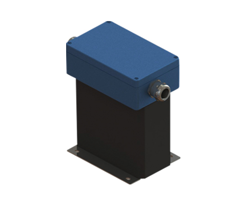
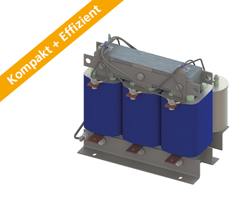
Motor Choke N CNW 854

Three-phase motor choke Description Compact & Efficient The new series not only scores points for its faster delivery time, but also for its resource conservation and increased efficiency. Reduce voltage rise (< 200V / µs) and distortions – optimally protect electrical consumers. In addition to voltage rises, there is a considerable amount of symmetrical and asymmetrical current distortions generated at the motor supply line due to the rapid switching of power semiconductors. These become more pronounced with increasing cable length. These disturbances can affect the motor’s performance through loud noises and, in extreme cases, through overheating. A motor choke can provide a remedy here. The motor choke reduces the voltage rise and voltage peaks between the conductors. Furthermore, the current is smoothed. Losses and heating are minimized and leakage current is reduced. Longer motor cable lengths can be used. The motor insulation is protected, thus increasing its lifespan. The motor choke also dampens conducted interference in the lower frequency range very well. Losses and typical noises in the motor laminations are reduced. Voltage rises are reduced to (< 200V / µs.) Increasing the service life of motors, lowering the edge steepness du / dt to earth and between the phases, reducing motor noise, and current smoothing. Advantages Protection for electrical consumers Limitation of voltage rise to < 200V/µs Extended service life of electrical consumers Reduction of engine noise Low leakage currents on the motor Longer motor cables are possible Easy construction Compact design Production possible according to UL insulation system E251513 TYPICAL APPLICATIONS Drive systems for motor drives, Mechanical engineering, Elevators / escalators, Pipes, Conveyor technology, Ventilation and air conditioning, Robotics, Automation technology, Power supplies, Wind turbines Technical Data Reduction of voltage rise du/dt to < 200V/µs Field frequency: 0 – 60 Hz Drive Switching frequency of the inverter: up to 150 A >4kHz, from 150 A >1.5kHz According to: EN 60289 / EN 61558 Test voltage: L-L 2500 V, AC/50Hz 60s; L-PE 2500 V, AC/50Hz 60s Insulation class: T40/F Protection rating: IP00 Climatic category: DIN IEC 60068-1 Overload: 1,5 x INenn 1 min / h Ambient temperature: 40 °C Design: standing on foot angle Technical specification Type Nominal voltage U [V] Nominal current I [A] Inductance L [mH] Losses P [W] Mass [kg] Mass Cu [kg] Mass Al [kg] N CNW 854 / 2 500 50 / 60 Hz 2 7,00 21 1,0 0,3 – N CNW 854 / 4 4 3,60 26 1,1 0,5 – N CNW 854 / 8 8 2,00 35 2,0 0,5 – N CNW 854 / 10 10 1,70 44 2,2 0,9 – N CNW 854 / 12 12 1,20 52 2,7 0,8 – N CNW 854 / 16 16 0,90 54 2,8 0,9 – N CNW 854 / 24 24 0,70 55 4,4 1,9 – N CNW 854 / 30 30 0,50 40 4,5 0,9 – N CNW 854 / 37 37 0,42 40 6,0 1,4 – N CNW 854 / 48 48 0,32 60 7,0 1,9 – N CNW 854 / 60 60 0,28 80 7,0 2,0 – N CNW 854 / 75 75 0,22 100 8,0 1,4 – N CNW 854 / 90 90 0,17 80 10,0 1,9 – N CNW 854 / 115 115 0,14 150 14,0 1,6 – N CNW 854 / 150 150 0,11 170 16,0 3,1 – N CNW 854 / 180 180 0,09 160 18,0 3,2 – N CNW 854 / 200 200 0,08 170 23,0 2,8 – N CNW 854 / 250 250 0,065 240 24,0 3,8 – N CNW 854 / 300 300 0,053 380 44,0 1,5 2,7 N CNW 854 / 350 350 0,046 330 55,0 2,6 4,6 N CNW 854 / 400 400 0,041 380 58,0 2,6 4,9 N CNW 854 / 500 500 0,032 520 63,0 2,6 5,2 N CNW 854 / 600 600 0,028 650 65,0 5,0 5,9 N CNW 854 / 700 700 0,024 820 86,0 5,0 5,7 N CNW 854 / 800 800 0,021 710 108,0 6,6 9,0 N CNW 854 / 900 900 0,018 800 114,0 13,8 7,6 N CNW 854 / 1000 1000 0,016 900 114,0 13,8 7,6 N CNW 854 / 1200 1200 0,013 1170 122,0 13,8 8,0 DIMENSIONS IN MM Type Length L1 [mm] Length L2 [mm] Width B1 [mm] Width B2 [mm] High max. H1 [mm] Fastening N1 [mm] Fastening N2 [mm] Fastening D1 [mm x mm] Clamp/ cable lug [mm²] Angle [mm x mm] Port A1 [mm] Port D2 [mm] PE Ø [mm] N CNW 854 / 2 80 96 45 55 110 56 34 5 x 8 2.5 – – – M4 N CNW 854 / 4 80 96 45 55 110 56 34 5 x 8 2.5 – – – M4 N CNW 854 / 8 80 96 55 65 110 56 43 5 x 8 2.5 – – – M4 N CNW 854 / 10 125 120 61 66 130 100 45 5 x 8 2.5 – – – M4 N CNW 854 / 12 125 120 71 67 130 100 55 5 x 8 2.5 – – – M4 N CNW 854 / 16 125 120 71 67 130 100 55 5 x 8 2.5 – – – M4 N CNW 854 / 24 155 150 76 86 170 130 54 8 x 12 10 – – – M4 N CNW 854 / 30 155 – 110 130 130 54 8 x 12 16 (M6) – 40 – M6 N CNW 854 / 37 155 – 125 130 130 69 8 x 12 16 (M6) – 40 – M6 N CNW 854 / 48 190 – 115 165 170 57 57 8 x 12 16 (M8) – 40 – M8 N CNW 854 / 60 190 – 115 165 170 57 57 8 x 12 16 (M8) – 40 – M8 N CNW 854 / 75 190 – 135 160 170 67 67 8 x 12 16 (M8) – 40 – M8 N CNW 854 / 90 190 – 135 160 170 77 77 8 x 12
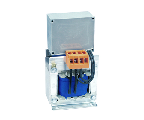
Harmonic Filter CNW 897

Three-phase harmonic filter (400 V / 50/60 Hz) DESCRIPTION The filter is designed for the reduction of the THD (Total Harmonic Distortion) when used with B12 rectifiers. The harmonic currents are extremely suppressed so that the THD is reduced to lower than 5 % (for example in UPS-systems).Typical values of Total Harmonic Distortion with B12 rectifiers and the use of transformers are between 12 and 13%. This complies with the EN 61000-3-4 and EN 61000-3-12 standards.If more severe conditions for the mains are defined, in addition to the transformer it is necessary to use REO-Harmonic-Filter type CNW 897. These filters are available in two different versions: THD < <5% THD < <10 % The IP00 version is especially suitable for panel mounting and can be mounted to save space here. The CNW 897 helps to comply with international power quality standards IEEE 519 or EN 61000-3. Advantages Reduction of the THDI value Low voltage drop Increasing network stability Reduction of the input current up to 30% Suitable for installation in control cabinets easy integration into existing systems Increased reliability of electrical installations Technical specification According to: EN 60289 / EN 61558 Test voltage: L-L 2500 V, DC 1min; L-PE 2500 V, DC 1min Insulation class: T40/F Climatic category: DIN IEC 60068-1 Protection: IP 00 (also available as IP20 version) Nominal voltage: 400V / 50 Hz Standards: IEEE 519, EN 61000-3-12, EN 61000-3-2, IEC 61000-3-4 Type Rated voltage /Rated frequency [V] Rated current 3x [A] Inductance 3x [mH] Capacity capacitor [μF] Rated power [kVA] Power dissipation [W] Cu /AI [kg] Weight throttle [kg] Weight Condi [kg] CNW 897/25/400/5% 3×400 50/60 Hz 25 2,9 3 x 68 17,3 70 9/ 0 20 5,98 CNW 897/40/400/5% 3×400 50/60 Hz 40 2,48 3 x 80 27,7 90 11/ 0 26 6,58 CNW 897/70/400/5% 3×400 50/60 Hz 70 1,1 3 x 180 48,5 130 18/ 0 32 10,18 CNW 897/90/400/5% 3×400 50/60 Hz 90 0,9 3 x 220 62,4 200 0.8/ 3.4 49 12,58 CNW 897/120/400/5% 3×400 50/60 Hz 120 0,75 3 x 220 + 3 x 40 83,1 250 0.8/5.1 59 17,66 CNW 897/150/400/5% 3×400 50/60 Hz 150 0,6 3 x 330 103,9 350 1/ 8.4 59 16,78 CNW 897/180/400/5% 3×400 50/60 Hz 180 0,5 3 x 330 + 3 x 180 124,7 330 1.1/ 8.4 65 21,86 CNW 897/250/400/5% 3×400 50/60 Hz 250 0,36 3 x 330 + 3 x 220 173,2 440 1.7/ 12.8 82 29,33 CNW 897/310/400/5% 3×400 50/60 Hz 310 0,3 6 x 330 214,8 570 1.9 /14 95 33,53 CNW 897/400/400/5% 3×400 50/60 Hz 400 0,225 6 x 330 +3 x 220 277,1 910 3 / 10.1 108 45,2 CNW 897/600/400/5% 3×400 50/60 Hz 600 0,2 9 x 330 415,7 1040 6.4 / 22.8 193 49,4