
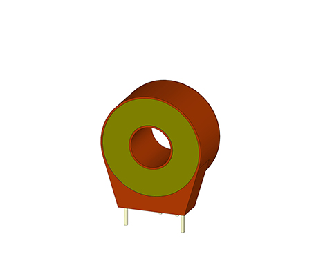
Passive Current Transformer Series IE MODULAR

Closed-loop current transformers DESCRIPTION In the case of bushing-type current transformers, the customer’s primary wire is pushed through the current transformer opening in the housing. The push-through opening depends on the size of the primary current.Wound primary-type current transformers have a primary winding and a secondary winding. Both windings are applied on the closed toroidal core and are isolated from each other by insulation. This principle applies mainly where primary currents are small. Low-voltage current transformers for the proportional transformation of large currents to directly measurable smaller current values Advantages Bolts or flat plug connection Bushing-type current transformers for direct conductor feedthrough Toroidal cores made of high-quality magnetic cores Frequency range 16 2/3 to 400 Hz optional High core output power and high-quality insulation (UL) circuits primaires et secondaires séparés électriquement Easy-to-assemble modular-type housing Variable connections, e.g. bolts, flat plugs, litz wires Wide range of housings with various push-through openings Typical applications Industry, Renewable energy sources, Railway engineering, Energy, automation and building technology Technical specification Type IE modular 500 1000 2500 IPN Primary rated current 500 1000 2500 [A] ImaxPN Max. Primary rated current 600 1200 3000 [A] IaN Secondary current 1000 [mA] RB Load resistance 5 15 30 [Ω] URB Load voltage 5 15 30 [V] PSek Power 5 15 30 [VA] KN Transmission ratio 500 1000 2500 Fi Measuring accuracy(50 Hz) 0,5 0,5 0,5 [%] f Frequency 50-400 [Hz] TA Ambient temperature -25 bis +70 [°C] Vp Insulation test 3 [KVac] Connection MS bolt / flat pin 6.3 x 0.8 [mm²] Weight 0,8 0,8 1,8 [kg] Standards 61869-2 Dimensions in mm Type I [mm] h1/h2 [mm] t1/t2 [mm] s1/s2 [mm] b1/b2 [mm] D [mm] D1xD2 [mm] f [mm] e [mm] x1/x2 [mm] IE modular 500 70 76/35 38/64 57/57 57/50 30,2 30,4×10,4 4,3 4,3 36/15 IE modular 1000 94 100/47 42/72 78/78 78/60 38,5 40,5×13,5 5,3 5,3 36/15 IE modular 2500 135 141/67,5 52/88 102/102 102/70 57,5 60,5×20,5 6,5 6,5 36/15 Data sheet Download our extensive catalog and discover many other REO products. Download Data sheet
Passive Current transformer Series IE (Pin Version)
Bushing-type current transformers (PIN version) Description In the case of bushing-type current transformers, the customer’s primary wire is pushed through the current transformer opening in the housing. The push-through opening depends on the size of the primary current. Wound primary type current transformers have a primary winding and a secondary winding. Both windings are applied on the closed toroidal core and are isolated from each other by insulation. This principle applies mainly where primary currents are small. Advantages PIN-Connection according to UL 94 V0 Bushing-type current transformers for direct conductor feedthrough Wound primary type current transformer, version for small currents Toroidal cores made of high-quality silicon-iron Measurement in the low-frequency range 16 2/3 to -400Hz High core output power and high-quality insulation (UL) circuits primaires et secondaires séparés électriquement des formes faciles à monter Variable connections, e.g. clamps, plugs, flat-cable plugs, flexible stranded wire or print mounting Wide range of housings with various push-through openings Technical specification Technical Data According to: EN/IEC 61869-1/2 Primary rated current: 1 – 50 A Frequency range: 50 – 400 Hz Type 1 3 5 10 25 50 2 Windings Through transformer Primary rated current [A] IPN 1 3 5 10 25 50 Max. Primary rated current [A] ImaxPN 1,2 3,6 6 12 30 60 Secondary current [mA] IaN 20 20 20 20 200 200 Power [VA] Psek 0,1 0,1 0,1 0,1 0,12 0,5 Ratio KN 50 150 250 500 1000 1000 Load resistance [Ω] RB 250 250 250 250 200 200 Load voltage [V] URB 5 5 5 5 5 10 Measuring accuracy 50 Hz [%] FU ≤ 1 ≤ 1 ≤ 1 ≤ 1 ≤ 1 ≤ 1 Ambient temperature [°C] TA -25 to + 70 -25 to + 70 -25 to + 70 -25 to + 70 -25 to + 70 -25 to + 70 Frequency range [Hz] f 50 – 400 50 – 400 50 – 400 50 – 400 50 – 400 50 – 400 Insulation test voltage [kVac] VP 3 3 3 3 3 3 Connection [mm²] 3-4/2-1 3-4/2-1 3-4/2-1 3-4/2-1 NC/2-1 NC/2-1 Weight [kg] 0,05 0,05 0,05 0,05 0,05 0,07 Standards EN/IEC 61869-1/2 Dimensions in mm Type PIN-connection [A] h [mm] b [mm] t [mm] DL [mm] s [mm] l [mm] a [mm] c [mm] IE/1 3-4/2-1 34 33 18 9 1,0 3,5 27,5 10 IE/3 3-4/2-1 34 33 18 9 1,0 3,5 27,5 10 IE/5 3-4/2-1 34 33 18 9 1,0 3,5 27,5 10 IE/10 3-4/2-1 34 33 18 9 1,0 3,5 27,5 10 IE/25 NC/2-1 34 33 18 9 1,0 3,5 27,5 10 IE/50 NC/2-1 38 38 20 13 1,0 6,5 30 10
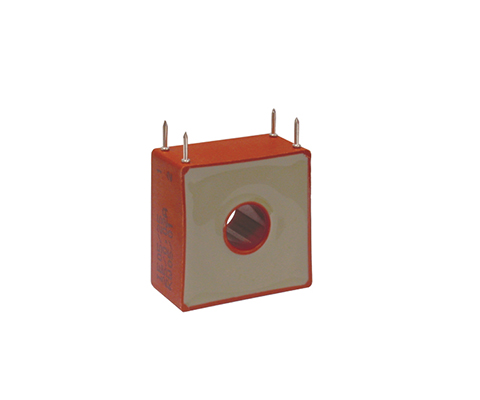
Passive Current Transformer Series Ie (Stranded Wire / Terminal)

Bushing-type current transformers Description In the case of bushing-type current transformers, the customer’s primary wire is pushed through the current transformer opening in the housing. The push-through opening depends on the size of the primary current. Wound primary type current transformers have a primary winding and a secondary winding. Both windings are applied on the closed toroidal core and are isolated from each other by insulation. This principle applies mainly where primary currents are small. Advantages Litz wires or terminals according to UL 94 V0 Bushing-type current transformers Wound primary type current transformer, version for small currents Toroidal cores made of high-quality silicon-iron Measurement in the low-frequency range 16 2/3 to -400Hz High core output power and high-quality insulation (UL) circuits primaires et secondaires séparés électriquement des formes faciles à monter Wide range of housings with various push-through openings UNIQUE SELLING POINT des formes faciles à monter Variable connections, e.g. clamps, plugs, flat-cable plugs, flexible stranded wire or print mounting Wide range of housings with various push-through openings Push-through openings Very long useful lifetime Typical applications Industry, Renewable energy sources, Railway engineering, Energy, automation and building technology Technical specification Type 50 100 300 500 1000 2000 3000 Primary rated current [A] IPN 50 100 300 500 1000 2000 3000 Max. Primary rated current [A] ImaxPN 60 120 360 600 1200 2400 3600 Secondary current [mA] IaN 1000 1000 1000 1000 1000 1000 1000 Power [VA] Psek 0,5 1,0 2,5 10 15 25 25 Ratio KN 50 100 300 500 1000 2000 3000 Load resistance [Ω] RB 0,5 1,0 2,5 10 15 25 25 Load voltage [V] URB 0,5 1,0 2,5 10 15 25 25 Measuring accuracy 50 Hz [%] FU 1,0 1,0 1,0 1,0 1,0 1,0 1,0 Ambient temperature [°C] TA -25 to + 70 -25 to + 70 -25 to + 70 -25 to + 70 -25 to + 70 -25 to + 70 -25 to + 70 Frequency range [Hz] f 50 to 400 50 to 400 50 to 400 50 to 400 50 to 400 50 to 400 50 to 400 Insulation test voltage [kVac] VP 3 3 3 3 3 3 3 Data sheet Download our extensive catalog and discover many other REO products. Download Data sheet Certifications
Passive Current Transformer Series IB
Current transformers for printed-circuit boards Description REO current transformers series IB are suitable for mounting on printed-circuit boards in the electric range of modern drive engineering for control purposes and measurement value logging. All safety regulations as for example double insulation are obtained. Advantages Low space requirement Suitable for PCB mounting Conforms to UL 94 V0 Classe de précision 1 Mesure dans la gamme de fréquences 50-400Hz faible erreur de phase pour la mesure de la puissance très faibles pertes d’inversion magnétique et de courants de Foucault circuits primaires et secondaires séparés électriquement des formes faciles à monter Technical specification Type IB 0,5/5 IB 0,5/20 IB 0,5/40 Courant primaire [A] IPN 0 – 5 0 – 20 0 – 40 Max. Primary rated current [A] ImaxPN 7 25 50 Secondary current[mA] IaN 0 – 10 0 – 25 0 – 40 Performance [VA] Psec 0 – 0,010 0 – 0,025 0 – 0,040 Rapport de transmission KN 1:500 1:800 1:1000 Résistance de charge [Ω] RB 100 40 25 Tension de charge [V] URB 0 – 1 Précision de mesure 50 Hz [%] FU ≤ 1 Température ambiante [°C] TA 0..+85 Frequency range [Hz] f 50 – 400 Insulation test voltage [kVac] VP 3 Dimensions in mm Type Primary current [A] Height [mm] Width [mm] Depth [mm] Opening [mm] PIN strength [mm] PIN length [mm] IB 05/5 0 – 5 30 26,5/17,5 14,5 10,5 0,7×0,7 5,0 IB 05/20 0 – 20 30 26,5/17,5 14,5 10,5 0,7×0,7 5,0 IB 05/40 0 – 40 30 26,5/17,5 14,5 10,5 0,7×0,7 5,0 Data sheet Download our extensive catalog and discover many other REO products. Download Data sheet Certifications
Toroidal fixed transformer
Three-phase isolating transformer Description The three-phase toroidal fixed transformer is used for protective separation between both alternating voltage networks (through double or reinforced insulation, optimal: shielding winding). Advantages Use in contamination levels of up to PD3 Protection class IP 00 to IP 54 (with terminal boxes) Shock and vibration-resistant design (upon request) Use of high-quality cores for the minimisation of power loss Flexible adjustment to customer specifications (modified voltage ratio, voltage taps, performance values, high level of protection, temperature monitoring, additional windings and alternative switch groups possible) Optional: All materials upon request in accordance with REO UL-System E251513 Standards: EN 61558 Technical specification Rated power 600 – 15.000 VA Input voltage 3 x 400; 3 x 230 V Output voltage 3 x 230; 3 x 400 V Rated current up to 3 x 22 A Frequency range 50 – 400 Hz Temperature class T40/E and T40/B % *Special voltages and higher powers on request Data sheet All data and configurations can be found in our product data sheet Download datasheet Certifications