
EMI-Filter CNW 102

Single-phase line filter (2 conductors, two-stage) DESCRIPTION Recommended filter for interference suppression according to EN 55011, Class B and EN 61800-3, Category C1. Cost-effective filter that is well-suited for direct mounting in the housing of an interference source due to its small dimensions and very good attenuation values in a two-stage design. The filter is also available as a version with low leakage current as well as a special medical version (without Y-capacitors). Optionally, the filter can also be supplied with overvoltage protection. A quick installation can be performed using connection with insulated flat connectors. However, versions with other connection options (terminal / wire) are also possible. ADVANTAGES Small dimensions quick connection touch-proof if used with insulated spade connectors very good damping performance at a low leakage current also as a medical version or with a lower leakage current available optional anti-surge protection UL approval for the complete model range – E217177 (not for N- and MED-versions) TYPICAL APPLICATIONS Applications: Switch-mode power supplies for industrial electronics, frequency converters for motor drives, power supply units, medical and telecommunication applications, DC applications TECHNICAL SPECIFICATION Conforming to: VDE 0565-3 / IEC 950 / UL 1283 Test voltage: L-N 2100 V, DC 1s, L/N-PE 2700 V, DC 1s Overload: 1,5 x I 1 min/h Climatic category: DIN IEC 68 Part 1 25/085/21 Type Rated voltage [V] Rated current [A] Leakage current [A][mA] Cx [μF] Cy nF] L [mH] R [kOhm] CNW 102/3 250 3 <3,5 0,94 20 13,6 560 CNW 102/6 250 6 <3,5 0,94 20 7,8 560 CNW 102/10 250 10 <3,5 0,94 20 3,6 560 CNW 102/16 250 16 <3,5 0,94 20 2,4 560 CNW 102/20 250 20 <3,5 0,94 20 2,0 560 CNW 102/3/N 250 3 <0,5 0,94 4,4 13,6 560 CNW 102/6/N 250 6 <0,5 0,94 4,4 7,8 560 CNW 102/10/N 250 10 <0,5 0,94 4,4 3,6 560 CNW 1022/16/N 250 16 <0,5 0,94 4,4 2,4 560 CNW 102/20/N 250 20 <0,5 0,94 4,4 2,0 560 CNW 102/3/MED 250 3 <0,005 0,94 – 13,6 560 CNW 102/6/MED 250 6 <0,005 0,94 – 7,8 560 CNW 102/10/MED 250 10 <0,005 0,94 – 3,6 560 CNW 102/16/MED 250 16 <0,005 0,94 – 2,4 560 CNW 102/20/MED 250 20 <0,005 0,94 – 2,0 560 DIMENSIONS IN MM Type Connection /PE-Connection B [mm] D [mm] H [mm] L1 [mm] L2[mm] L3[kOhm] CNW 102/3 Flat plug 6,3×0,8 50 5,3 40 87 75 65 CNW 102/6 Flat plug 6,3×0,8 50 5,3 40 87 75 65 CNW 102/10 Flat plug 6,3×0,8 50 5,3 40 87 75 65 CNW 102/16 Flat plug 6,3×0,8 53 5,3 40 110 100 90 CNW 102/20 Flat plug 6,3×0,8 53 5,3 40 110 100 90 Data sheet Download our extensive catalog and discover many other REO products. Download Datenblatt Certifications
EMI-Filter CNW 101

Single-phase line filters (2 lines, single-stage) DESCRIPTION Recommended filter for interference suppression according to EN 55011, Class A and EN 61800-3, Category C2. Cost-effective filter that, due to its small dimensions and good attenuation values with a single-stage design, is well-suited for direct mounting in the housing of an interference source. The filter is also available as a version with low leakage current as well as a special medical version (without Y-capacitors). Optionally, the filter can also be supplied with overvoltage protection. The connection with insulated flat connectors allows for quick and touch-safe installation. However, versions with other connection options (terminal / stranded wire) are also possible. ADVANTAGES Small dimensions quick connection touch-proof if used with insulated spade connectors good damping performance at a low leakage current also available as a medical version or with a lower leakage current optional anti-surge protection UL approval for the complete model range – E217177 (not for N- and MED-versions) TYPICAL APPLICATIONS Switch-mode power supplies for industrial electronics, telecommunications, data systems engineering and DC applications. TECHNICAL SPECIFICATION Conforming to: VDE 0565-3 / IEC 950 / UL 1283 Test voltage: L-N 2100 V, DC 1s, L/N-PE 2700 V, DC 1s Overload: 1,5 x I 1 min/h Climatic category: DIN IEC 68 Part 1 25/085/21 Type Nominal voltage [V] Nominal current [A] Leakage current [mA] Cx [μF] Cy nF] L [mH] R [kOhm] CNW 101/3 250 3 <3,5 0,94 20 3,3 560 CNW 101/6 250 6 <3,5 0,94 20 1,8 560 CNW 101/10 250 10 <3,5 0,94 20 1,8 560 CNW 101/16 250 16 <3,5 0,94 20 1,2 560 CNW 101/20 250 20 <3,5 0,94 20 1,0 560 CNW 101/3/N 250 3 <0,5 0,94 20 3,3 560 CNW 101/6/N 250 6 <0,5 0,94 20 1,8 560 CNW 101/10/N 250 10 <0,5 0,94 20 1,8 560 CNW 101/16/N 250 16 <0,5 0,94 20 1,2 560 CNW 101/20/N 250 20 <0,5 0,94 20 1,0 560 CNW 101/3/MED 250 3 <0,005 0,94 – 3,3 560 CNW 101/6/MED 250 6 <0,005 0,94 – 1,8 560 CNW 101/10/MED 250 10 <0,005 0,94 – 1,8 560 CNW 101/16/MED 250 16 <0,005 0,94 – 1,2 560 CNW 101/20/MED 250 20 <0,005 0,94 – 1,0 560 DIMENSIONS IN MM Type Connection /PE-Connection B [mm] D [mm] H [mm] L1 [mm] L2 [mm] L3 [kOhm] CNW 101/3 Flat plug 6,3×0,8 45 4,2 30 70 60 52 CNW 101/6 Flat plug 6,3×0,8 45 4,2 30 70 60 52 CNW 101/10 Flat plug 6,3×0,8 50 5,3 30 85 75 65 CNW 101/16 Flat plug 6,3×0,8 50 5,3 30 85 75 65 CNW 101/20 Flat plug 6,3×0,8 50 5,3 30 85 75 65 Data sheet Download our extensive catalog and discover many other REO products. Download Datenblatt Certifications
REOTRON MDZ 2000

Ignition and Control Device DESCRIPTION The control devices of the REOTRON MDZ2000 series are microprocessor-controlled devices for controlling power thyristors in 6-pulse rectifier systems. The devices include the control and regulation electronics as well as the ignition pulse generation and the ignition pulse output stages. The rectifier can be operated as a current regulator or voltage regulator, with an automatic switchover to the smaller setpoint. The required setpoints can be specified by external potentiometers, control signals 0…10 V, DC or 0…20 mA / 4…20 mA DC or via the integrated control display. The actual value inputs are standardly designed for +/- 0…40 V rectifier output voltage and +/- 0…75 mV output current, but 0…10 V, DC normalized input signals are also possible. Function The REOTRON MDZ control and ignition devices are designed for controlling rectifier systems. They contain one controller each for current and voltage regulation. In voltage regulation mode, the output voltage specified by the setpoint is kept constant by an internal control loop, so load changes or mains voltage fluctuations have no influence on the output voltage. If the device is operated as a current regulator, the output current of the device is compared with the setpoint and the device output is regulated accordingly. The output voltage can rise up to the maximum value. Reaching the limit values Imax and control limit is indicated by LEDs. If both setpoints are used during operation, the controller with the smaller setpoint always has priority. This means that, for example, in voltage regulation with underlying current regulation, the voltage regulator is active as long as the permitted current value is not exceeded. If the current limit is reached, the current regulator has priority. If the device is to operate as a pure voltage or current regulator, the other setpoint input must be bridged to the reference voltage (10 V, DC). ADVANTAGES Use as three-phase thyristor controller or fully controlled three-phase bridge Connection to clockwise or counterclockwise rotating field possible (self-detecting) Current or voltage regulation Selection option for transformer vector group Switchable to controller operation without control functions External setpoint specification Input for overtemperature switch Fault indication Usable as three-phase thyristor controller with downstream transformer and passive bridge rectifier TECHNICAL SPECIFICATION Device type REOTRON MDZ 2000 Mains connection 3x 400 V +6%-10% 50/60 Hz Ignition pulse stages 6 Pulse voltage approx. 12 V Pulse current 500 mA Transformer vector groups Dd0, Yy0, Dz0, Dy5, Yd5, Yz5,Dd6, Yy6, Dz6, Dy11,Yd11, Yz11 and Primary controller Voltage setpoint 0…10 V, DC / 0…20 mA / 4…20 mA / Pot 10 kΩ Current setpoint 0…10 V, DC / 0…20 mA / 4…20 mA / Pot 10 kΩ Actual value input voltage +/- 0…40 V (0…10 V, DC option) Actual value input current +/- 0…100 mV (0…10 V, DC option) Ramp-up/down integrator 0.1…10 seconds adjustable Voltage controller PI controller P-component adjustable Current controller PI controller P-component adjustable Input impedance actual value input voltage 56 kΩ Input impedance actual value input current 5.6 Ω Control signal pulse enable 12…24 V, DC / 2.5 mA Control signal setpoint lock 12…24 V, DC / 2.5 mA Overtemperature input Switch 1 mA Fault relay 1 changeover contact load 250 V, 1 A Status relay 1 changeover contact load 250 V, 1 A Permissible Ambient temperature 0…45 ° C Dimensions (WxHxD) 140x290x160 mm
3-phase thyristor power controller REOTRON MDW 700

3-phase thyristor power controller Description The REOTRON MDW power controllers are used in industrial process engineering and especially in thermal engineering systems. The thyristor controllers are available as phase-angle devices and with period group control and have internal voltage, current and power controllers – so the output power remains stable even with high requirements. The devices can work both directly on the load to be regulated (e.g. in infrared heaters) and as primary controllers of transformers for voltage adjustment and safe isolation (e.g. in graphite heating elements). Thyristor controllers of the REOTRON MDW series (3 controlled phases) are modern microprocessor-controlled devices with integrated measuring devices for the actual values of voltage and current transformers. Outputs (actual value monitor) with 0…+10V, DC are available for processing the actual values in external system components. Communication with the devices can take place via analog interfaces 0… +10 V, DC, 0(4)… 20 mA, potentiometers or field bus systems Profibus-DP, CAN bus, DeviceNet, EtherNet/IP, ProfiNet and EtherCAT, thus enabling integration into existing bus systems. The devices can be adapted to the respective load conditions via internally adjustable parameters Umax, Imax, Pmax as well as ramp-up ramp and ramp-down ramp. The REOTRON MDW 700 thyristor controllers are designed as switch cabinet installation devices with protection class IP 20 for mounting on a mounting plate. The cooling type is air cooling, fans are integrated from 150 A. The devices in the REOTRON MDW-WK series are designed for water cooling and can be easily integrated into an existing water circuit. Advantages phase-angle or burst-fire controllers measuring of effective values connection via analog interfaces, potentiometers or field bus systems Air or water- cooling installation device for control cabinets Technical specification REOTRON MDW 700-10 3 x 400 V AC, +/- 10% 3 x 0…400 V 3 x 10 A REOTRON MDW 700-25 3 x 400 V AC, +/- 10% 3 x 0…400 V 3 x 25 A REOTRON MDW 700-50 3 x 400 V AC, +/- 10% 3 x 0…400 V 3 x 50 A REOTRON MDW 700-80 3 x 400 V AC, +/- 10% 3 x 0…400 V 3 x 80 A REOTRON MDW 700-110 3 x 400 V AC, +/- 10% 3 x 0…400 V 3 x 110 A REOTRON MDW 700-150 3 x 400 V AC, +/- 10% 3 x 0…400 V 3 x 150 A REOTRON MDW 700-200 3 x 400 V AC, +/- 10% 3 x 0…400 V 3 x 200 A REOTRON MDW 700-300 3 x 400 V AC, +/- 10% 3 x 0…400 V 3 x 300 A REOTRON MDW 700-115* 3 x 400 V AC, +/- 10% 3 x 0…400 V 3 x 115 A REOTRON MDW 700-160* 3 x 400 V AC, +/- 10% 3 x 0…400 V 3 x 160 A REOTRON MDW 700-250* 3 x 400 V AC, +/- 10% 3 x 0…400 V 3 x 250 A REOTRON MDW 700-350* 3 x 400 V AC, +/- 10% 3 x 0…400 V 3 x 350 A REOTRON MDW 700-450* 3 x 400 V AC, +/- 10% 3 x 0…400 V 3 x 450 A Load Type Resisive/ Induktive Target Value: Storm, Voltage, Power 0…+10 V, DC 0(4)…20 mA Internal keyboard Interface (optional) Profibus-DP, CAN-Bus, DeviceNet, EtherCAT Release Input 24 V, DC, external contact (potential-free) Status update ready , status update power on Relay, changeover contact Relay, changeover contact Display for effective value : Current/Voltage 0…+10 V, DC Betriebstemperatur 0…+45°C Storage/ Transport temperature -10…+70°C IP Code IP 20 * with water cooling
1-Phase thyristor-controller REOTRON MEW 700

The REOTRON MEW power controllers are predestined for applications in the process industry, especially in thermal engineering systems.
1-Phase thyristor-controller REOTRON EW 514

The REOTRON EW 514 is a single-phase thyristor power regulator for load currents up to 6 A.
The control electronics are isolated from the mains voltage. The REOVIB 509 is designed for controlling bowl or linear feeders up to 15 A current rating. The output frequency 50Hz/100Hz (60Hz/120Hz) is selected to suit the feeder. In the regulation circuit there is built-in compensation for mains variations.
1-phase thyristor controler REOTRON EW 509

REOTRON EW 509 is a single-phase thyristor control for currents up to 15 A. The control electronics is free of mains potential. The REOVIB 509 is designed for controlling bowl or linear feeders up to 15 A current rating. The output frequency 50Hz/100Hz (60Hz/120Hz) is selected to suit the feeder. In the regulation circuit there is built-in compensation for mains variations.
DC-Power supply REOTRON SMP-LM
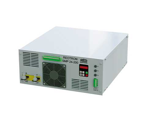
The DC power supplies from the REOTRON SMP series are primary switched-mode power supplies with galvanic isolation from the input to the output. The devices can be used as voltage, current or power regulators.
DC-Power supply REOTRON SMP-SMB
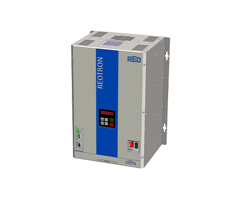
The DC power supplies from the REOTRON SMP series are primary switched-mode power supplies with galvanic isolation from the input to the output. The devices can be used as voltage, current or power regulators.
DC-Power supply REOTRON SMP-KMB
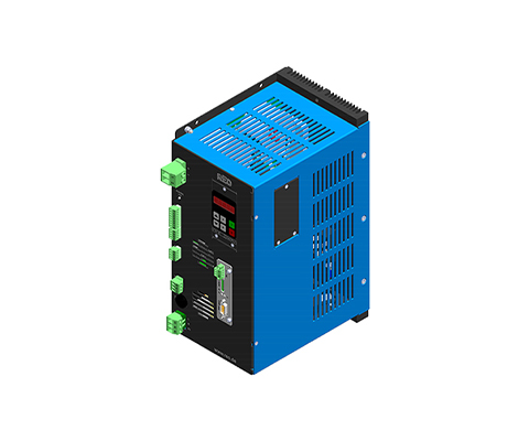
The DC power supplies from the REOTRON SMP series are primary switched-mode power supplies with galvanic isolation from the input to the output. The devices can be used as voltage, current or power regulators.