
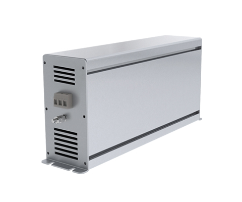
Railroad transformer NTT 400 U
On-board power supply transformer Description The REO transformer NTT 400 D is designed for on-board power supplies, which are fed by theauxiliary converter. The transformer NTT 400 D is the complete, ready to use-unit with transformer, mounting frame and housing. The transformer is used to adapt the voltage and for galvanic isolation of the pulse-width modulated DC link voltage and the consumers of the vehicle electrical system. An appropriate sinusoidal filter must be connected between the transformer and the inverter. The secondary-side load of the isolating transformer can be switching devices, rotating machines, resistive loads and semiconductor converter devices. The transformers are designed for the use of vehicles in the AC or DC grid (in inverter mode) in containers. This guarantees that transformers from REO are optimally designed for your application. Maximum service life, cost/benefit optimization and safety are the focal points of our development work. Power. 10 – 30 kVA Rated voltage Primary: Rated voltage: (Normal operation): 3×440 Veff 60 Hz Rated voltage: (external power supply): 3×400 Veff 50 Hz Rated voltage: (reduced operation): 3×345 Veff 47 Hz Secondary: Voltage: 3×230 Veff Operating temperature: -25 ° C … + 55 ° C (optional + 75 ° C) Humidity: max 95% Pollution degree: PD4 Insulation class: F/H Test voltage: EN 50124 / EN 60310 Vibration resistance: Cat.1 class A/B acc. to EN61373 Voltages: 24 / 42 / 110 / 230 / 400 / 690 Volt (Optional) Switching group: Optional Customer-specific components On-board power transformers can be customized. Are you interested in this product? Please contact us! In addition to standardized components for use in converters, REO offers customer-specific products – as individual components or as a complete solution in a container. The benchmark in railroad technology is the availability and safety of passengers. Here, REO offers special solutions that are developed step by step in close cooperation with the customer. Advantages Vibration and shock tested according to DIN 61373 Cat 1 Class B High efficiency Low idling losses Reduced field scattering Low noise Reduced weight High mechanical resistanceNatural Cooling Pollution degree PD4 Various performance classes Technical specification Rated power: 10000 – 30000 VA Input voltage: 3×440 V Type Performance[kVA] Total weight[kg] Copper weight[kg] Efficiency [%] Uk[%]* NTT 400 U/15.0 15.0 96 29 97.1 2.6 NTT 400 U/20.0 20.0 126 36 97.4 2.3 NTT 400 U/25.0 25.0 150 51 97.5 2.5 NTT 400 U/30.0 30.0 175 57 97.8 2.1 DIMENSIONS IN MM Type L [mm] B1 [mm] B2 [mm] H [mm] N1 [mm] N2 [mm] D [mm] Mass [kg] NTT 400 U/15.0 510 520 350 345 385 460 10 120 NTT 400 U/20.0 540 520 355 365 410 440 13 147 NTT 400 U/25.0 575 500 355 396 455 440 13 175 NTT 400 U/30.0 561 536 392 351 300 456 13 195
Stray field transformer RUT 500
Leakage Transformer Description Particularly in the railway sector when the highest possible level of comfort and safety for the passengers is important, space-saving, safe and long-lived components are essential. Current dips or voltage losses can cause various undesirable effects, such as loss of motor power. The REO leakage transformer ensures harmonized current and voltage outputs, filtering harmonics, and limiting the ripple current.With the spatial separation of the primary and secondary windings and the resulting intentional increase in the magnetic leakage field, the REO leakage transformer achieves a loose magnetic coupling.This results in the combination of the function of a transformer (transforming voltage with galvanic separation) and a current-limiting choke. Options Various performance classes: 50 kVA, 100 kVA, 150 kVA and 200 kVA Voltage drop 10% UK,20%, and 30% Voltage ratio /Windings selectable Winding material and optimized insulation degree selectable Advantages Space-saving (transformer and choke in a single component) Longer life for motors by limiting of current peaks Low-cost Optimized for railway operation (high degree of pollution , Shock- and vibration tested ,Salt spray and immersion tested) Technical specification Rated power: 71000 – 275000 VA Input voltage: 210 – 1660 V
EMC FILTER CNW 307
Filter combination (single stage) Description The CNW 307 combi filter relieves the supply network by compensating the harmonic reactive power. The harmonics are reduced to THD < 60 %. This improves efficiency and reduces the load on the line. The mains choke also limits the mains interference that occurs, such as current peaks and voltage dips in the mains. To comply with the EN 610003-2 or IEEE 519 standard, we recommend using the CNW 898 series. The integrated mains filter attenuates the very high asymmetrical and symmetrical HF currents caused by the inverter. Advantages Compact design Different connections (Terminals/cables /bars) Easy installation Attenuation of current harmonics Limitation of inrush currents Reduction of mains disturbance, current peaks and voltage drops The increased life time for IGBTs Low-noise Typical applications Applications: Interference suppression of frequency converters with IGBTs with simultaneous reduction of harmonics PFC (Power Factor Correction) and commutation (current transition between thyristors) in fast-switching power semiconductors. Reduction of THD values (Total Harmonic Distortion). Technical specification Conforming to: VDE 0565-3-1 / EN 133200 Test voltage: L-L 2100 V, DC 1s, L-PE 2700 V, DC 1s Overload: 1,5 x I 1 min/h Climatic category: DIN IEC 60068-1 (1) Voltage drop of line choke: The line choke of the CNW 307/3 and CNW 307/6 has a Uk of 4 % For current ratings of 10 A off the line, chokes have a Uk of 2 %. Leakage current of the mains filter: The maximum leakage current under normal working conditions is shown in the technical table. If two phases are interrupted, the leakage current can increase 6-fold. For Europe:Short circuit voltage Uk: 2% (at 400 V) Voltage drop: 4,6 V/branch For America:Frequency: 60 Hz Short circuit voltage Uk: 4,8% (at 200 V) Voltage drop: 5,5 V/branch Type Rated voltage[V] Rated current[A] Inductance[mH] Leakage current [mA] Copper[kg] Weight[kg] CNW 307/3 up to 3 x 500 3 9,70 >15 0,7 2,3 CNW 307/6 up to 3 x 500 6 4,88 >15 0,8 2,8 CNW 307/10 up to 3 x 500 10 1,46 >15 1,2 2,8 CNW 307/16 up to 3 x 500 16 0,91 >15 1,9 3,9 CNW 307/25 up to 3 x 500 25 0,58 >15 2,4 5,2 CNW 307/36 up to 3 x 500 36 0,41 >15 3,5 5,8 CNW 307/50 up to 3 x 500 50 0,29 >30 4,6 9,4 DIMENSIONS IN MM Type Options Connection Dimensions [mm] Terminal Fig. 1 Cable Fig. 2 L 1 L 2 L 3 B 1 B 2 H A1 A2 D CNW 307/3 4 mm² 1,5 mm² 167 153 136 90 60 175 1500 1000 7 CNW 307/6 4 mm² 1,5 mm² 167 153 136 90 60 175 1500 1000 7 CNW 307/10 4 mm² 1,5 mm² 167 153 136 90 60 175 1500 1000 7 CNW 307/16 6 mm² 2,5 mm² 207 193 176 90 60 175 1500 1000 7 CNW 307/25 6 mm² 4 mm² 307 293 276 90 60 175 1500 1000 7 CNW 307/36 10 mm² 6 mm² 307 293 276 90 60 175 1500 1000 7 CNW 307/50 16 mm² 10 mm² 387 373 356 90 60 175 1500 1000 7 Certifications
EMI-Filter REO CNW 304

Filter combination (single stage) Description By using a line reactor the upper harmonics are reduced and the starting current is limited. This increases the efficiency and discharges the leads. Advantages Easy installation Small footprint Reduction of cable looms in control panels Attenuation of higher harmonics Low hum vacuum impregnated choke Reduced start-up current The choke is rated for a short-circuit voltage of 4%, at rated current, as standard Typical applications Interference suppression of frequency converters with IGBTs and reduction of harmonics (conforming to VDE 0160/EN 61800-3 class B) Technical specification Conforming to: VDE 0565-3 / IEC 950 / UL 1283 Test voltage: L-L 2100 V, DC 1s, L-PE 2700 V, DC 1s Overload: 1,5 x I 1 min/h Climatic category: DIN IEC 68 Part 1 25/085/21 Type Nominal voltage [V] Nominal current [A] Leakage current[mA] L [mH] Cx [µF] Cy [nF] Rx [k] Ry [k] CNW 304/80 3×400 80 >35 1,2 1,5 600 560 560 CNW 304/120 3×400 120 >35 0,5 3,5 870 560 560 CNW 304/150 3×400 150 >35 0,6 3,5 870 560 560 DIMENSIONS IN MM Type Connections Dimensions [mm] Clamp Earth L 1 L 2 L 3 B 1 B 2 H 1 CNW 304/80 50 mm² M10 330 315 290 190 120 216 CNW 304/120 50 mm² M10 440 420 400 280 200 248 CNW 304/150 50 mm² M10 440 420 400 280 200 248 Certifications
du/dt choke CNW M 833

Fully encapsulated three-phase dv/dt Filter (IP20) Description Reduce voltage rise to < 500V / µs – protect electrical loads and insulation cost-effectively. A simple and inexpensive method of reducing the rate of voltage rise is to use a du / dt filter. The filter dampens the voltage rise to acceptable values and prevents overvoltages on long supply lines. Losses and heating are minimised and the leakage current is reduced. By limiting the voltage gradient, the motor insulation is protected and the service life is extended. EMC interference in the radiation range from 1 MHz to 30 MHz is also reduced. Voltage rises are reduced to < 500V / µs. Advantages Optimal mechanical protection of the reactor Optimal mechanical protection of the choke Protection for electrical consumers Limit the voltage rise to <500V/µs Extended service life of electrical consumers Low leakage currents on the motor Reduced losses Very low noise Easy construction Production possible according to UL insulation system E251513 Typical applications Drive systems for motor drives: Mechanical engineering, Elevators / escalators, Pipes, Conveyor technology, Ventilation and air conditioning, Robotics, Automation technology, Power supplies and Wind turbines Technical specification Type Protection class Nominal voltage[V] Rated current[A] Inductance[mH] Capacity[pF] Weight[kg] Clamp[mm²] Cable gland CNW M 833 / 8 Protection class up to IP 66 3 x 400 ≥ 60 Hz 8 2 330 3,3 2,5 M20x1,5 CNW M 833 / 16 Protection class up to IP 66 16 0,9 330 4,5 6 M25x1,5 CNW M 833 / 36 IP 65 36 0,42 1500 9 16 M32x1,5 CNW M 833 / 60 IP 65 60 0,27 2200 25 35 M40x1,5 CNW M 833 / 90 IP 65 90 0,17 4700 27 35 M40x1,5 CNW M 833 / 180 IP 65 175 0,09 10000 40 95 M63x1,5 DIMENSIONS IN MM Type Dimensions L1 [mm] L2 [mm] L3 [mm] B1 [mm] B2 [mm] B3 [mm] B4 [mm] B5 [mm] H1 [mm] H2 [mm] H3 [mm] N1 [mm] N2 [mm] D [mm] CNW M 833 / 8 170 140 150 80 80 55 20,5 5,5 170 57 75 135 65 5,5×7 CNW M 833 / 16 180 140 170 85 80 65 10,5 5,5 170 57 75 155 70 5,5×7 CNW M 833 / 36 245 175 175 115 120 80 20 20 250 140 110 155 95 5,5×15 CNW M 833 / 60 315 249 255 180 175 120 30 27 323 218 105 185 150 9×13 CNW M 833 / 90 315 250 255 180 175 120 30 25 325 218 105 185 150 9×13 CNW M 833 / 180 355 270 – 127 200 160 105 8 350 220 130 185 105 10×18 Data sheet Download our extensive catalog and discover many other REO products. Download Data sheet Certifications
Phase angle controllers REOVIB SMART SYSTEM
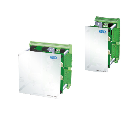
IP00, for assembly on a DIN rail Description REOVIB Smart system basic module In an open design for mounting on a DIN rail with an output channel of max. 6 A with level control/level switch. The basic module has a power supply for extension modules. This means that additional output modules can be added up to a total current of 10 A. REOVIB Smart system extension module In open design for mounting on a DIN rail. The extension module has one output channel max. 6 A with level control/exchange circuit and can be installed together with the basic module and several extension modules. REOVIB SMART SINGLE In open design for mounting on a DIN rail with an output channel of max. 6 A. Advantages Cost-effective phase-angle control systems with vital functionality Can be used as a standalone device or in modular design for control of a complete feed system Output current up to 6A DIN rail mounting Versions available with fill level/overflow control Typical applications Weighing systems, multiple-head weighing wagon, conveyor & assembly automation, sorting systems Technical specification Type SMART Single SMART Basic module SMART Expansion module Mains input 110/ 230 V switchable 110/ 230 Vswitchable via SMART Basic module Mains frequency 50 / 60 Hz +/- 3 Hz 50 / 60 Hz +/- 3 Hz via SMART Basic module Output voltage 20 … 100V/ 40…210 V 20 … 100V/ 40…210 V 20 … 100V/ 40…210 V Output current max. 6 A max. 6 A max. 6 A Vibration frequency 50 … 100 Hz (60 / 120 Hz) 50 … 100 Hz (60 / 120 Hz) 50 … 100 Hz (60 / 120 Hz) Setpoint value Poti, 0 … 10 V, 0 (4) … 20 mA Poti, 0 … 10 V, 0 (4) … 20 mA Poti, 0 … 10 V, 0 (4) … 20 mA Ext. Enable 24 V DC, Switch 24 V DC, Switch 24 V DC, Switch U min / U max Internal potentiometer Internal potentiometer Internal potentiometer Soft start fixed fixed fixed Max. Output current from all outputs – 10 A – Fill level / overflow control – ✓ ✓ Conformity CE, RoHS CE, RoHS CE, RoHS Protection class IP00 IP00 IP00 Data sheet Download our extensive catalog and discover many other REO products. Download Data sheet Certifications
Phase angle controllers REOVIB SMART SYSTEM MINI
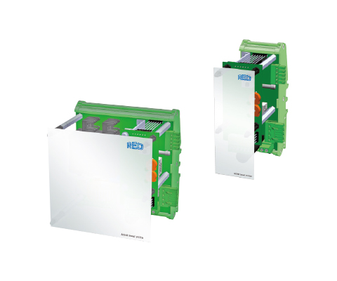
IP00, for assembly on a DIN rail Description REOVIB SMART SYSTEM MINI basic module REOVIB SMART SYSTEM basic module in open design for assembly on a DIN rail with an outputchannel of max. 6A with fill level/overflow control.The basic module has a supply for expansion modules, so further output modules up to a totalcurrent of 10A can be connected. REOVIB SMART SYSTEM MINI expansion module In open design for DIN rail mounting. An expansion module has one output channel max. 1A and can be set up together with the basic module and several expansion modules. Advantages Cost-effective phase-angle control systems with vital functionality Can be used as a standalone device or in modular design for control of a complete feed system Output current up to 6A DIN rail mounting Versions available with fill level/overflow control Typical applications Weighing systems, multiple-head weighing wagon, conveyor & assembly automation, sorting systems Technical specification Type SMART mini Basic module SMART mini Expansion module Mains input 110/ 230 V autom. recognition via SMART mini Basic module Mains frequency 50 / 60 Hz +/- 3 Hz via SMART mini Basic module Output voltage 20 … 100V/ 40…210 V 20 … 100V/ 40…210 V Output current max. 6 A max. 6 A Vibration frequency 50 … 100 Hz (60 / 120 Hz) 50 … 100 Hz (60 / 120 Hz) Setpoint value Poti, 0 … 10 V, 0 (4) … 20 mA Poti, 0 … 10 V, 0 (4) … 20 mA Ext. Enable 24 V DC, Switch 24 V DC, Switch U min / U max internal potentiometer internal potentiometer Soft start fixed fixed Max. Output current from all outputs 15 A – Fill level / overflow control – – Conformity CE, RoHS CE, RoHS Protection class IP00 IP00 Data sheet Download our extensive catalog and discover many other REO products. Download Data sheet Certifications
Phase angle controllers REOVIB SMART ATS 100

IP54 design for mounting directly on the vibrating machine, single output Description REOVIB ATS 100 devices are available in an IP 54 housing with output currents up to 15 A andare listed by UL.The control devices are available with input cable /output cable. The devices offer the most important functions for use in vibratory conveyor technology and therefore represent a cost-effective option for controlling vibratory conveyors – and in a high-quality design. The devices are available in various protection classes – as a control cabinet installation module in IP20 or as a housing variant in IP54 for direct mounting on the application. The housing variants with protection class IP54 are available in different versions: Input cable/output cable Input cable/output socket Complete cable connection solution for mains, output and control connections. Advantages Cost-effective phase-angle control systems with vital functionality IP54-Version for mounting directly on the vibrating machine or IP20-Version fas a module for mounting in a switch cabinet Versions available with UL approval (SMART ATS 100) Output current up to 15 A Typical applications Conveyor & assembly automation, conveyor technology, sorting systems Technical specification Mains input 110/ 230 V switchable Mains frequency 50 / 60 Hz +/- 3 Hz Output voltage 20 … 100V/ 40…210 V Output current max. 15 A Vibration frequency50Hz 50 Hz / 100 Hz Vibration frequency 60Hz 60 Hz / 120 Hz Setpoint value Poti, 0 … 10 V, 0 … 20 mA Ext. Enable 24 V DC, Switch Setting Umin/ Umax Internal potentiometer Soft start fixed Mains voltage compensation – Conformity UL, CE, RoHS Protection class IP54 Ambient temperature 0…45°C Certifications Optional UL-certified
Phase angle controllers REOVIB SMART 6A
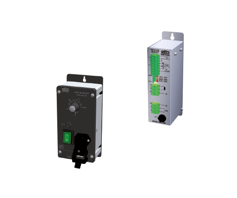
IP54 or IP20 Description The REOVIB SMART series includes phase angle control units for use in vibratory conveyor applications. The devices offer the most important functions for use in vibratory conveyor technology and therefore represent a cost-effective option for controlling vibratory conveyors – and in a high-quality design. The devices are available in various protection classes – as a control cabinet installation module in IP20 or as a housing variant in IP54 for direct mounting on the application. The housing variants with protection class IP54 are available in different versions: Input cable/output cable Input cable/output socket Complete cable connection solution for mains, output and control connections The REOVIB SMART ATS 100 devices are available in an IP54 housing design with output currents up to 15 A and are UL-listed. Advantages Cost-effective phase-angle control systems with vital functionality IP54-Version for mounting directly on the vibrating machine or IP20-Version fas a module for mounting in a switch cabinet Versions available with UL approval (SMART ATS 100) Output current up to 6A Typical applications Conveyor & assembly automation, sorting systems Technical specification Mains input 110/ 230 V switchable Mains frequency 50 / 60 Hz +/- 3 Hz Output voltage 20 … 100V/ 40…210 V Output current max. 6A Vibration frequency50Hz 50 Hz / 100 Hz Vibration frequency 60Hz 60 Hz / 120 Hz Setpoint value Poti, 0 … 10 V, 0 … 20 mA Ext. Enable 24 V DC, Switch Setting Umin/ Umax Internal potentiometer Soft start fixed Mains voltage compensation – Conformity CE, RoHS Protection class IP20/ IP54 Ambient temperature 0…45°C Data sheet Download our extensive catalog and discover many other REO products. Download Data sheet Certifications Optional UL-certified
Phase angle controllers REOVIB SMART-MIC
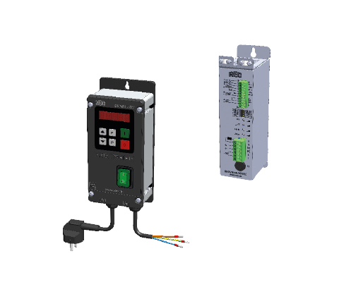
IP54 or IP20 Description In contrast to the previous model, the new built-in LED display allows exact values to be set the same way every time. This ensures more precise settings and easier traceability of the entries. Thanks to the connection to Industry 4.0 and IIoT readiness, with the REOVIB SMART-MIC you are already securing the possibilities for the communication technology of the future. Just like the predecessor devices, the devices in the REOVIB SMART-MIC series are also available in various protection classes – as a control cabinet installation module in IP20 or as a housing variant in IP54 for direct mounting on the application. The housing variants with protection class IP54 are available in different versions: Input cable/output cable Input cable/output socket Completely pluggable with input plug and output socket In addition to the functions and benefits of the REOVIB SMART series, the control unit has mains voltage compensation for constant amplitude and an adjustable soft start ramp time. Advantages LED display Mains voltage compensation IP54-Version for mounting directly on the vibrating machine or IP20-Version fas a module for mounting in a switch cabinet Output current up to 6A Typical applications Conveyor & assembly automation, conveyor technology, sorting systems Technical specification Mains input 110/ 230 V switchable Mains frequency 50 / 60 Hz +/- 3 Hz Output voltage 20 … 100V/ 40…210 V Output current max. 6A Vibration frequency50Hz 50 Hz / 100 Hz Vibration frequency 60Hz 60 Hz / 120 Hz Setpoint specification LED display,0 … 10 V, 0 (4) … 20 mA* Ext. Enable 24 V DC, Switch Umin/ Umax setting LED display (IP54) / potentiometer (IP20) Soft start adjustable 0…60 Sec. Mains voltage compensation ✓ Conformity CE, RoHS Protection class IP20/ IP54 Ambient temperature 0…40°C * Optional for IP54 Data sheet Download our extensive catalog and discover many other REO products. Download Data sheet Certifications